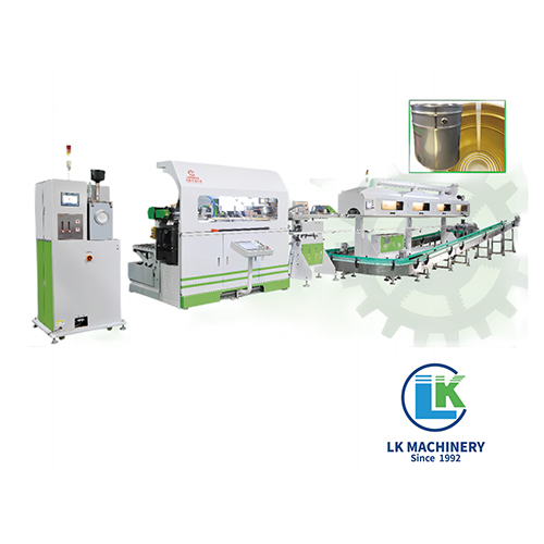
A 1-5L square can production line is built around a series of purpose-engineered machines and subsystems that work in a continuous, synchronized flow. The core components include: a sheet feeding system, blanking and forming machine, side seam welder, stripe coater, interior spray coater, curing oven, expanding machine, flanging machine, seaming machine, leak tester, printing unit, handle assembly station, and palletizing system — all coordinated by a central PLC-based control platform. Each component contributes a specific function, and the failure or misalignment of any single unit directly impacts overall line output, can quality, and material yield. Understanding what each component does, its critical parameters, and how it connects to adjacent equipment is essential for engineers specifying a new line, maintenance teams troubleshooting downtime, and procurement managers evaluating equipment.
The sections below examine every major component in depth, with the technical specifications and performance benchmarks that define a well-engineered line.
Sheet Feeding System
The sheet feeding system is the entry point of the entire production line. Its job is to separate individual tinplate or tin-free steel (TFS) sheets from a stack and deliver them one at a time to the downstream blanking press at a controlled, consistent rate. Because downstream machines operate at fixed speeds, any variation in feed timing creates gaps or jams that disrupt the entire line.
Modern feeders use a vacuum suction cup array mounted on a servo-driven carriage. The suction cups lift one sheet at a time, a pneumatic air-blast "fanning" system separates the top sheet from the one below, and double-feed detection sensors (typically ultrasonic or optical) verify that only a single sheet has been picked before it is advanced. If a double-feed is detected, the sheet is diverted automatically without stopping the line.
Key Specifications
- Sheet thickness range: 0.18 mm to 0.32 mm
- Sheet size range: typically 400 mm × 300 mm up to 800 mm × 600 mm depending on can size
- Feed rate: synchronized with blanking press, typically 30–120 strokes per minute
- Sheet alignment accuracy: ±0.3 mm to ensure correct blank geometry downstream
- Stack height capacity: up to 500 mm before reloading, minimizing operator intervention frequency
A lubricating roller station is often integrated into the feeder to apply a thin film of food-grade or industrial oil to the sheet surface before forming, reducing tooling wear by up to 40% and preventing galling on the forming dies.
Blanking and Notching Press
The blanking press cuts the fed sheet into precise rectangular blanks sized for the specific can format being produced. For a 1 L square can, a blank of approximately 230 mm × 160 mm is typical; a 5 L can requires a blank closer to 450 mm × 320 mm. Simultaneously, the press applies corner notches — small angular cuts at each corner of the blank — that allow the metal to fold cleanly at the can body corners without wrinkling or cracking.
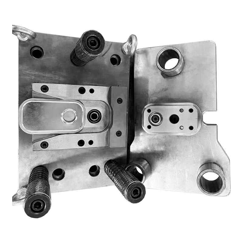
The press tooling consists of a hardened steel punch and die set with clearances of 5–10% of sheet thickness. Tighter clearances produce cleaner cut edges but increase tooling wear; wider clearances extend die life but risk burr formation on blank edges. The blanks are then transferred — either by mechanical finger transfer or vacuum pick-and-place — directly to the forming station.
Material utilization is a critical economic parameter at this stage. Efficient blank nesting on the sheet can achieve material yields above 88%, while poor nesting may waste 15–20% of the raw material cost.
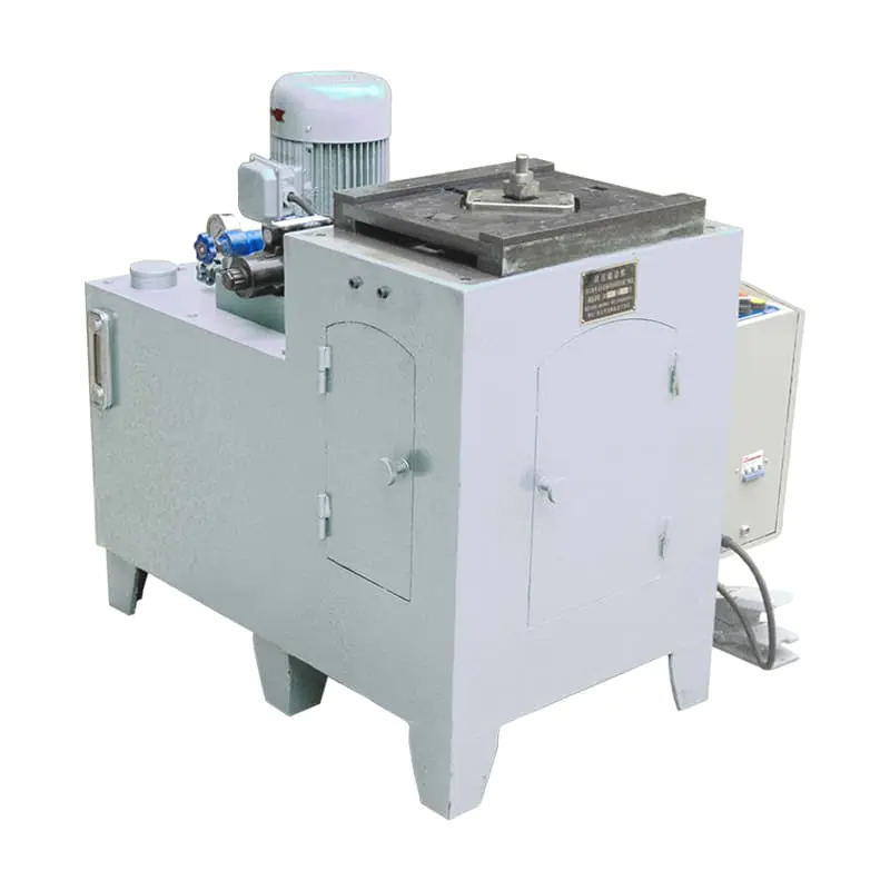
Can Body Forming Machine
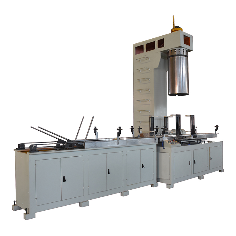
The can body forming machine is the mechanical heart of the line. It takes flat blanks and bends them progressively into the final rectangular tube shape that becomes the can body. This is achieved through a series of forming stations, each applying a bend at a specific location until the blank is folded into a box profile with the two long edges brought together along one face to form the side seam.
The critical tooling elements are the forming mandrel (which defines the internal dimensions of the can body) and the bending fingers and pressure rollers that wrap the blank around it. For square cans, the mandrel must have sharp, well-defined corners to produce the characteristic rectangular profile. Corner radii on finished can bodies are typically held to 1.0–3.0 mm depending on can size and material grade.
Forming Machine Technical Highlights
- Can body dimensional tolerance: ±0.3 mm on width and height
- Forming speed: up to 100 bodies per minute on high-output lines
- Quick-change mandrel system: tooling swap between can sizes in under 20 minutes
- Side seam joint type: lock-seam or open-seam for subsequent welding
- Compatible materials: tinplate T2–T4, TFS, blackplate with lacquer
Side Seam Welding Unit
After forming, the two abutting edges of the can body along the vertical side seam must be permanently joined. The side seam welder is the component responsible for this, and its quality directly determines the pressure integrity and service life of the finished can.
The dominant technology on modern 1-5L square can lines is high-frequency electric resistance welding (ERW), operating at frequencies between 150 kHz and 450 kHz. At these frequencies, current concentrates at the surface of the overlapping seam edges (the skin effect), generating localized heat that fuses the metal in milliseconds without the addition of filler wire. The result is a weld bead 0.3–0.5 mm wide whose tensile strength equals or exceeds the base material.
Laser welding is an alternative used when superior cosmetic appearance or ultra-narrow heat-affected zones are required, though equipment investment is substantially higher. For most square can production in the 1-5 L range, ERW offers the optimal balance of speed, cost, and reliability.
Welding Unit Performance Parameters
| Parameter |
ERW (High-Frequency) |
Laser Welding |
| Welding speed |
60–100 m/min |
20–60 m/min |
| Weld bead width |
0.3–0.5 mm |
0.1–0.3 mm |
| Heat-affected zone |
Moderate |
Very narrow |
| Filler material needed |
No |
No |
| Inline weld inspection |
Eddy current / optical |
Optical / thermal imaging |
| Best suited for |
High-volume standard cans |
Premium / specialty cans |
Comparison of ERW and laser welding technologies for square can side seam joining
An integrated online weld quality monitor using eddy current testing evaluates every seam at full production speed, rejecting cans with pinholes, cold welds, or burn-through before they proceed to coating.
Stripe Coating Applicator
Welding destroys the protective tin or pre-applied lacquer layer at the seam. Without repair, this bare steel strip would corrode rapidly when in contact with food, beverages, or chemicals. The stripe coater — positioned immediately after the welder — applies a narrow band of liquid lacquer to the interior and sometimes exterior weld zone, restoring corrosion protection before the lacquer is cured downstream.
The applicator uses either a roll-on wheel system or a precision spray nozzle. Roll-on systems are preferred for consistent film thickness control; spray systems offer more flexibility for varying can widths. The stripe width is controlled to 6–10 mm — wide enough to guarantee full coverage of the heat-affected zone, narrow enough to minimize wasted lacquer.
- Stripe width control: ±1 mm tolerance
- Film weight: typically 4–8 g/m² wet applied
- Lacquer types: epoxy, polyester, or organosol depending on can end-use
- Drying: pre-dried by a short IR zone before full oven curing
Interior Spray Coating System
For cans intended to hold food products, lubricants, solvents, agrochemicals, or other reactive contents, a full interior spray coating system applies a continuous lacquer film to the entire inner surface of the can body. This coating prevents metal-content interaction, extends shelf life, and ensures regulatory compliance with food-contact material standards such as FDA 21 CFR and EU Regulation No. 1935/2004.
The spray system uses airless or air-assisted spray nozzles mounted on a manifold inside a spray booth. The can body passes over the nozzle at controlled speed while the nozzle oscillates to ensure uniform coverage on all four interior walls. Film weight is controlled to 5–12 g/m² — too little leaves uncoated spots; too much causes adhesion failure or coating drips.
Interior Coating Material Selection by Can Application
| Coating Type |
Typical Can Use |
Key Benefit |
Curing Temp (°C) |
| Epoxy Phenolic |
Food, oil, paint |
Excellent chemical resistance |
180–210 |
| Polyester |
Lubricants, coatings |
Solvent resistance, hard film |
180–200 |
| Organosol |
General industrial |
High flexibility, good adhesion |
170–200 |
| Water-based Epoxy |
BPA-free food packaging |
Low VOC, regulatory compliance |
160–190 |
Interior lacquer selection depends on contents type, regulatory requirements, and process temperature capability
Curing Oven
The curing oven converts the liquid lacquer applied at the stripe and spray coating stations into a hard, cross-linked, chemically resistant film. This is a thermally driven process: the lacquer resins undergo polymerization reactions when exposed to temperatures in the range of 160–210 °C, with the specific profile depending on the lacquer chemistry and the can material's heat tolerance.
Modern curing ovens on square can lines use a combination of infrared (IR) pre-heating and hot-air convection curing zones. IR pre-heating rapidly brings the can body surface temperature up in the first zone, reducing the total oven length required. Convection zones then maintain the peak metal temperature (PMT) — the parameter that actually drives cure — at the target value of 190–200 °C for 30–60 seconds, which is sufficient for most epoxy phenolic and polyester lacquers.
- Oven zones: typically 3–5 zones with independent temperature control
- Air circulation: high-velocity fans ensure uniform temperature across can cross-section
- Heat recovery: exhaust heat recirculation reduces energy consumption by 25–30%
- Cooling zone: exits oven at below 40 °C to allow safe handling by downstream equipment
- VOC exhaust treatment: afterburner or activated carbon system for solvent-based lacquers
Insufficient curing leaves a soft, under-crosslinked film that fails adhesion and chemical resistance tests. Over-curing causes lacquer embrittlement and cracking during subsequent forming steps such as flanging and seaming. The oven control system therefore maintains temperature uniformity within ±5 °C across the full width and length of the curing zone.
Expanding Machine
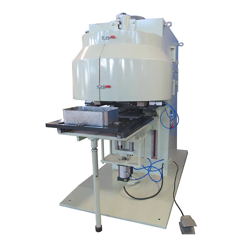
After curing, the can body is dimensionally calibrated by the expanding machine. This component inserts a precisely machined expanding mandrel into the can body and pushes it outward against the sidewalls, correcting any springback, twist, or dimensional variation introduced during forming. The process sets the final internal dimensions of the can body to tolerances of ±0.2 mm, which is critical for lid fitment accuracy at the seaming station.
The expanding machine also performs beading on many square can designs: horizontal ribs pressed into the can sidewalls that significantly increase column strength. A beaded 5 L square can made from 0.22 mm tinplate can achieve the same stacking strength as an un-beaded can made from 0.28 mm material, representing a substantial material cost saving at high volumes.
- Body squareness after expanding: ±0.2 mm
- Bead depth and pitch: customizable to application requirements
- Stacking strength improvement from beading: 30–40%
- Mandrel changeover time: typically under 15 minutes per size change
Flanging Machine
The flanging machine prepares both open ends of the can body for lid attachment by bending the edges outward at a precise angle to create the seaming flange. This outward-turned lip is what the double-seaming machine interlock with the lid hook to form the hermetic seal.
Flanging for square cans is mechanically more demanding than for round cans. At the four corners, the metal must stretch outward over a very small radius without cracking. Purpose-designed corner relief geometry in the flanging tooling distributes the strain across a slightly larger arc at each corner, preventing micro-cracks that would be invisible to the naked eye but would allow leakage after filling. Flanging speed is typically 40–100 cans per minute with both ends flanged simultaneously.
Critical Flange Dimensions
| Dimension |
Target Value |
Consequence of Deviation |
| Flange width |
1.8–2.2 mm |
Narrow = weak seam; wide = material waste and corner cracking |
| Flange angle |
90° ± 2° |
Incorrect angle causes poor lid seating before seaming |
| Flange uniformity |
±0.2 mm across perimeter |
Non-uniform flange leads to seam height variation |
| Corner crack inspection |
Zero visible cracks |
Micro-cracks cause leakage after filling |
Critical flange dimensions and the impact of deviations on downstream seaming quality
Double Seaming Machine
The double seaming machine is arguably the most quality-critical component on the line. It joins the bottom lid to the can body (and on filling lines, the top lid after filling) using a two-roll mechanical interlocking process that creates a hermetic, pressure-resistant seal without adhesives or sealants — relying only on mechanical geometry and a thin bead of sealing compound applied to the lid countersink.
The process works in two sequential operations. First operation rolls curl the lid hook over the body flange, forming the initial interlock. Second operation rolls then compress and iron the assembled seam, flattening the five layers of metal into a tight, well-defined cross-section. A properly formed double seam on a square can has a seam height of 2.8–3.2 mm, a seam thickness of 1.0–1.3 mm, and a body hook overlap of at least 45% of the available overlap length.
Because square cans have flat sides and corners, the seaming machine must be specifically designed for square-profile chucks and seaming rolls. Round-can seamers cannot be adapted for this application. At corners, the seaming rolls must transition smoothly to avoid wrinkling or false seam formation.
- Seaming speed: 30–100 cans per minute depending on can size
- Seam verification: periodic destructive tear-down testing every 30–60 minutes
- Chuck design: matched to specific can body dimensions; non-interchangeable between round and square
- Sealing compound: pre-applied to lid countersink; typically rubber-based, food-contact approved
Lid Press and Lid Feeding System
While not always physically integrated into the main can body line, the lid press and lid feeder are essential companion components. The lid press cuts circular or square-profile lids from tinplate sheet, forms the countersink profile, and applies sealing compound in a continuous operation. The compound is applied as a liquid by a rotary compound lining machine and then oven-cured before the lids are transferred to the seamer.
The lid feeder delivers lids one at a time to the seaming machine from a stacked magazine, using a de-stacking mechanism with controlled suction and air separation. Feed timing is synchronized with the arrival of can bodies at the seamer. A misfeed or double-lid event triggers an automatic stop to prevent seaming defects.
- Lid material: same tinplate or TFS as can body, typically same or slightly heavier gauge
- Compound application accuracy: ±0.5 mm on compound bead position
- Lid magazine capacity: typically 200–500 lids before refill required
- Lid feed rate: matched to seaming machine speed
Leak Testing System
Once the bottom lid is seamed on, every single can on a modern production line is subjected to a non-destructive leak test before it is accepted. This is a zero-tolerance inspection: a leaking can reaching a customer causes product spoilage, liability claims, and brand damage that far outweigh the cost of any individual can.
The most widely used method is pressurized air decay testing. A test head seals both the open top and the seamed bottom of the can. Compressed air at 15–30 kPa is introduced, and any pressure drop over a defined dwell period — typically 0.1–0.3 seconds at high-speed lines — is detected by a sensitive pressure transducer. Even a pinhole of 0.05 mm diameter produces a measurable pressure decay. Rejected cans are automatically diverted to a reject chute without stopping the line.
Well-maintained lines using quality materials typically achieve reject rates below 0.05% — fewer than 5 cans per 10,000 produced. A sudden increase in the reject rate is a primary diagnostic indicator of problems at the seaming or flanging station.
Printing and Exterior Decoration Unit
The printing unit applies product graphics, regulatory information, and branding to the exterior of the can body. This can be a standalone module or integrated into the main production line. Two primary technologies are used on 1-5L square can lines:
- Offset lithographic printing: 2–6 color stations, UV-curable or solvent inks, resolution of 150–200 lpi; best suited for high-volume runs where amortizing plate costs is feasible
- Digital inkjet printing: no plates required, variable data capability (batch codes, expiry dates), shorter setup time; ideal for short runs or products requiring unique serialization
An overvarnish applicator and secondary curing zone follows the print station to protect the ink layer from abrasion during downstream handling, transport, and shelf life. Lines without inline printing are configured to apply a clear base lacquer to the exterior for label adhesion, or left plain for the filling customer to apply pressure-sensitive labels.
Handle Assembly and Accessory Attachment Station
Square cans of 2.5 L and above typically include a carry handle for ergonomic handling by end users. The handle assembly station automatically feeds wire bail handles or stamped D-handles from a vibratory bowl feeder, inserts lug brackets into pre-punched holes or embossed bosses on the can body, and crimps or rivets them in place. Pull-out strength of properly riveted handles on a 5 L can typically exceeds 150 N — well above the force required to carry a full can.
Additional accessories installed at this station may include:
- Pour spout bosses or F-style spout openings for lubricant and chemical cans
- Threaded neck inserts for screw-cap closure compatibility
- Tamper-evident bands applied over cap threads
- Plastic or metal locking caps assembled by pick-and-place heads
All accessory feeders are monitored by sensors for empty-bowl or jam conditions, with automatic line alerts to prevent the assembly of incomplete cans.
Vision Inspection System
A machine vision inspection system, comprising multiple high-resolution cameras and image processing software, evaluates cans at key points along the line for defects that pressure testing alone cannot detect. Vision systems typically check:
- Seam geometry: height, thickness, and visible defects such as droop, vee, or false seam
- Coating uniformity: uncoated spots, runs, or contamination on interior and exterior surfaces
- Can body squareness and sidewall flatness: detects collapsed corners or buckled panels
- Print registration and color accuracy: compared against stored reference images
- Dents, scratches, or surface contamination: physical handling damage
Modern vision systems process images at up to 120 frames per second, maintaining full 100% inspection even at maximum line speed. Statistical reports generated by the vision system enable process engineers to identify trends — for example, a gradual increase in sidewall dent frequency indicating a worn guide rail — before they cause significant scrap loss.
Conveyor and Transfer System
The conveyor and transfer system connects all stations on the line, maintaining controlled spacing, orientation, and speed of cans as they move from one process to the next. On a 1-5L square can line, conveyors must accommodate the wide range of can sizes — from a compact 1 L body to a tall 5 L body — without can tip-over or jamming. Adjustable guide rails and variable-speed drives allow the same conveyor to handle the full size range.
Transfer points between stations — particularly the in-feed to the seamer and the exit from the leak tester — use starwheel feeders or servo-driven picker arms to ensure precise timing without mechanical shock that could dent freshly formed cans. An accumulation conveyor section between the main line and the palletizer buffers the output of the line during minor interruptions at the palletizer, preventing upstream stoppages from false alarm shutdowns.
PLC-Based Control System and HMI
The entire 1-5L square can production line is coordinated by a programmable logic controller (PLC) or distributed control system (DCS) that synchronizes the speed, timing, and fault response of all stations. The PLC communicates with individual machine controllers over a fieldbus network (typically Profinet, EtherNet/IP, or DeviceNet), collecting sensor data and issuing control commands in real time.
Operators interact with the system through a touchscreen Human-Machine Interface (HMI) panel displaying live production data, alarm status, and process trends. Recipe management allows operators to switch between can size and material combinations with a few screen touches, with the PLC automatically loading the corresponding speed, temperature, and pressure parameters. This capability reduces changeover time from hours to under 30 minutes on well-engineered systems.
Control System Capabilities Summary
| Feature |
Function |
Benefit |
| Recipe management |
Store and recall parameters per can size |
Changeover in under 30 minutes |
| Real-time monitoring |
Display speed, temp, pressure, reject count |
Immediate visibility of process deviations |
| Alarm and fault management |
Auto-stop with fault location displayed |
Faster troubleshooting, less scrap |
| Remote diagnostics |
OEM access via Ethernet / VPN |
Faster remote support, reduced downtime |
| Energy monitoring |
Per-station power consumption tracking |
OEE reporting, sustainability targets |
| Production data logging |
Per-pallet traceability records |
Quality audit trail, material traceability |
Key control system features and their operational benefits on a 1-5L square can production line
Stacking and Palletizing System
The stacking and palletizing system is the final output stage. Empty finished cans are nested — stacked open-end-up inside one another — to achieve the maximum transport density for delivery to filling facilities. A 10-unit nest of 5 L square cans occupies approximately the same pallet footprint as a single filled can, reducing empty-can logistics costs substantially.
A robotic palletizer or layer-forming gantry arranges the nested stacks on standard Euro or industrial pallets (1200 mm × 1000 mm or 1200 mm × 800 mm). Stretch-wrap stations apply film to the completed pallet for transport stability. Pallet weight and stack count data are logged automatically for inventory management and shipping documentation.
- Palletizing speed: matched to line output, typically 10–30 pallets per hour
- Stack height per pallet: determined by can size and safe transport weight
- Accumulation buffer: absorbs minor palletizer interruptions without stopping the main line
- Automatic pallet dispensing: integrated pallet dispenser eliminates manual forklift intervention at the palletizer in-feed
Component Integration: How the Systems Work Together
No individual component on a 1-5L square can production line operates in isolation. The performance of each station affects every station downstream, and the system is only as fast as its slowest bottleneck. The table below summarizes all major components, their role in the production flow, and the key performance metric by which each is evaluated.
| Component |
Primary Function |
Key Performance Metric |
| Sheet Feeding System |
Separate and deliver sheets |
Alignment accuracy ±0.3 mm; zero double feeds |
| Blanking and Notching Press |
Cut blanks and corner notches |
Blank dimension ±0.2 mm; material yield >88% |
| Can Body Forming Machine |
Bend blank into rectangular tube |
Body dimension ±0.3 mm; up to 100/min |
| Side Seam Welder |
Fuse vertical body seam |
Zero pinholes; weld speed 60–100 m/min |
| Stripe Coater |
Repair weld zone lacquer |
Stripe width 6–10 mm ±1 mm |
| Interior Spray Coater |
Full interior surface protection |
Film weight 5–12 g/m²; uniform coverage |
| Curing Oven |
Harden lacquer film |
PMT 190–200 °C ±5 °C for 30–60 s |
| Expanding Machine |
Calibrate body dimensions and bead |
Body squareness ±0.2 mm |
| Flanging Machine |
Form lid attachment flange |
Flange width 1.8–2.2 mm; no corner cracks |
| Lid Press and Feeder |
Form and feed lids with compound |
Compound position ±0.5 mm; zero double-lids |
| Double Seaming Machine |
Join lid to body with double seam |
Hook overlap ≥45%; seam height 2.8–3.2 mm |
| Leak Testing System |
100% seal integrity verification |
Detect ≥0.05 mm pinhole; reject rate <0.05% |
| Vision Inspection System |
Surface and dimensional quality check |
100% inspection at up to 120 fps |
| Printing Unit |
Apply exterior graphics |
Print registration; 2–6 color offset or digital |
| Handle Assembly Station |
Attach handles and accessories |
Handle pull strength >150 N |
| PLC Control System |
Coordinate all line functions |
Changeover <30 min; real-time fault response |
| Stacking and Palletizing System |
Stack and palletize finished cans |
10–30 pallets/hour; pallet stability |
All major components of a 1-5L square can production line with primary function and key performance metric
Choosing a Supplier for a Complete Square Can Production Line
A production line is only as reliable as the engineering and after-sales support behind it. When evaluating suppliers, the key factors are: whether the supplier designs and manufactures all core components in-house or assembles third-party machines, the depth of application knowledge for square-can-specific tooling (particularly seaming and flanging), the availability of spare parts, and the responsiveness of technical service.
LK Machinery Co., Ltd. is a professional manufacturer of complete 1-5L square can production lines, based in Zhoushan City on the coast of the East China Sea. Located in the Siqian Community, Dinghai Cengang Street, adjacent to the Yongzhou Cross-sea Expressway, the company benefits from convenient water and land transportation links that facilitate equipment delivery to both domestic and international customers. Its comprehensive manufacturing capability covers the full range of components described in this article — from sheet feeding and forming through welding, coating, curing, seaming, inspection, and palletizing — providing customers with a single-source solution and unified accountability for line performance.


 +86 13666712509

 English
 русский
 عربى
عربى

Contact Us