The production process for a Vacuum Cleaner Pail Production Line follows a tightly sequenced chain of metal forming, joining, surface treatment, and assembly operations that transform flat steel coil stock into finished, painted, and assembled vacuum cleaner pail housings ready for motor and component installation. The core sequence is: coil feeding and blanking, deep drawing and re-drawing, trimming and flanging, seam welding or mechanical joining, surface cleaning and pre-treatment, painting or powder coating, drying and curing, dimensional inspection, and final assembly preparation.
A fully integrated vacuum cleaner pail production line is typically designed around a continuous flow manufacturing philosophy, where each process station is synchronized to a common takt time — the cycle time per unit determined by dividing the available production time by the required output rate. For a typical industrial pail vacuum cleaner housing line targeting 1,200 to 2,400 units per shift, the takt time is 10 to 30 seconds per unit, requiring all process stations to complete their operations within this window to maintain line balance and avoid bottlenecks.
Understanding each stage in detail — the equipment required, the process parameters controlled, the quality checkpoints applied, and the common failure modes addressed — is essential for manufacturers designing new production lines, engineers troubleshooting existing lines, and procurement teams specifying line equipment. The following sections cover each production stage comprehensively.
Stage 1: Raw Material Preparation — Coil Stock Selection and Feeding
The production process begins with the incoming raw material: cold-rolled steel coil stock, selected to match the structural and forming requirements of the vacuum cleaner pail housing design. The material specification directly determines the formability, surface quality, weld reliability, and corrosion resistance of the finished housing.
Steel Grade and Thickness Selection
Vacuum cleaner pail housings are typically formed from cold-rolled low-carbon steel (SPCC or equivalent grade per JIS G3141, or DC01/DC03 per EN 10130) in thicknesses ranging from 0.5 mm to 0.8 mm depending on the pail diameter, required structural rigidity, and end-use load requirements (some industrial wet-dry vacuum pails must support static loads from the vacuum motor assembly above and liquid content below). The relevant material properties for deep drawing formability are:
- Plastic strain ratio (r-value): A minimum r-value of 1.4 is generally specified for deep-drawn pail housing components, indicating strong resistance to thinning during drawing. Higher r-values allow deeper draws with reduced risk of tearing at the punch radius.
- Strain hardening exponent (n-value): Higher n-values (typically 0.20 to 0.26 for deep-drawing grades) indicate better distribution of plastic strain across the forming zone, reducing strain localization that causes fracture
- Total elongation: Minimum 38% elongation (A80) is typical for deep-drawing grades, providing sufficient ductility reserve for multi-stage redrawing without intermediate annealing
- Surface finish designation: Bright-rolled or temper-rolled surface (FB or FC per EN 10130) provides the surface roughness Ra of 0.6 to 1.6 micrometers required for good paint adhesion without additional surface preparation
(Source: EN 10130:2006 Cold rolled low carbon steel flat products for cold forming; JIS G3141 Cold Reduced Carbon Steel Sheet and Strip.)
Coil Feeding System
Steel coils are loaded onto a hydraulic decoiler that unwinds the coil under controlled tension. The coil passes through a straightening unit — typically a 7- to 9-roller leveler — that removes the coil curvature (coil set) and cross-bow deformation inherent in wound coil stock. Uncorrected coil set causes blank misregistration in the blanking die and dimensional inconsistency in the drawn shell.
After the straightener, a servo-driven feed system advances the strip into the blanking or progressive die at the calculated pitch (the distance between successive blank centers) synchronized to the press stroke. Modern servo feeds achieve pitch accuracies of plus or minus 0.05 mm, ensuring consistent blank weight and symmetry that directly affects drawing quality. The complete coil handling system — decoiler, straightener, servo feed — is typically integrated into a single compact unit designed to handle coil weights of 3 to 8 tonnes for uninterrupted production runs of several hours between coil changes.
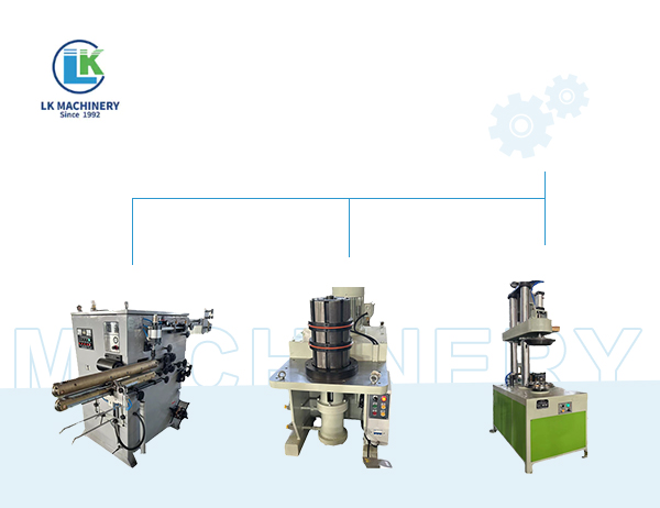
Stage 2: Blanking — Cutting the Circular Starting Blank
The first forming operation is blanking: cutting a circular disc (blank) from the flat strip stock. This blank is the starting form from which all subsequent drawing operations develop the pail housing shape. The blank diameter is a critical process variable — it determines the total surface area available for forming into the pail sidewall and base, and must be calculated precisely from the part geometry using the surface area equivalence principle.
Blank Diameter Calculation
The theoretical blank diameter (D) for a simple cylindrical cup is calculated from the surface area relationship:
D = square root of (d squared + 4dh)
Where d is the cup inner diameter and h is the cup height. For a vacuum cleaner pail housing with complex profiles, flanges, and radii, this formula is extended by the DIN 8584 part surface area calculation method, or validated computationally using finite element simulation of the forming process before tool manufacture. An incorrectly sized blank — even by 2 to 3 mm in diameter — results either in insufficient material reaching the flange (causing edge cracking) or excess material in the flange zone (causing wrinkling). (Source: DIN 8584-3 Manufacturing processes — Deep drawing; Lange, K., Handbook of Metal Forming, Society of Manufacturing Engineers.)
Blanking Die Design and Burr Control
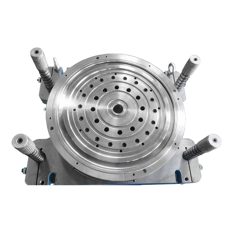
The blanking die consists of a circular punch and a matching die ring with a controlled clearance between them. For 0.6 mm sheet steel, the recommended die clearance per side is 6 to 10% of material thickness — approximately 0.036 to 0.060 mm — to produce a clean shear face with minimal burr height. Excessive clearance produces a large rollover and burr that can cause drawing die scoring; insufficient clearance causes secondary fracture and a rough shear face that increases drawing tool wear.
Blanking presses for pail production typically operate at 40 to 80 strokes per minute with progressive die tooling that may perform blanking and first draw in a single press stroke, reducing handling between operations and improving blank-to-draw dimensional consistency.
Stage 3: Deep Drawing and Re-Drawing — Forming the Pail Body
Deep drawing is the core metal forming operation in the vacuum cleaner pail production line. It transforms the flat circular blank into a three-dimensional cup or shell by pressing the blank over a punch and into a die cavity, causing the material to flow inward from the flange zone and form the cylindrical or tapered sidewall of the pail housing.
Drawing Ratio and Multi-Stage Drawing Sequence
The drawing ratio (DR) for a single draw operation is defined as the blank diameter divided by the punch diameter (D/d). The maximum drawing ratio achievable in a single draw without fracture is typically DR = 1.8 to 2.2 for standard deep-drawing steel grades. For a vacuum cleaner pail housing with a body diameter of approximately 250 mm and a height of 300 to 400 mm, the required blank diameter may be 550 to 650 mm, giving an overall drawing ratio of 2.2 to 2.6 — exceeding the single-draw limit.
This requires a multi-stage drawing sequence: typically 2 to 4 drawing stages (first draw, first redraw, second redraw, and final sizing draw) depending on the pail geometry and material grade. Each stage reduces the shell diameter while increasing the shell height, with the drawing ratio of each stage kept below the material's safe single-stage limit. Intermediate annealing — heat treatment to restore ductility lost through work hardening — may be required between drawing stages for deep or complex profiles, though modern deep-drawing steel grades (DC05 and DC06 per EN 10130) may avoid this requirement for pail depths achievable in 3 stages.
Blank Holder Pressure and Lubrication
During each drawing stage, a blank holder (pressure pad) applies controlled pressure to the flange zone of the blank to prevent wrinkling as the material flows inward. Blank holder pressure is one of the most critical process variables:
- Too low blank holder pressure: The flange zone buckles under compressive stress and wrinkles form on the sidewall — an irreversible defect requiring scrap
- Too high blank holder pressure: Friction between the blank holder and the flange material exceeds the allowable drawing force and the cup base or sidewall fractures — also irreversible scrap
- Optimum blank holder pressure for 0.6 mm deep-drawing steel is typically in the range of 2 to 5 MPa, applied by hydraulic or nitrogen gas cylinders in the press tooling
Lubrication is applied to both faces of the blank before each drawing stage to reduce tool-workpiece friction and prevent galling (metal transfer from workpiece to tool surface). Deep-drawing oil — a mineral oil with extreme-pressure additives — is applied by roller coating or spray at a rate of 1 to 3 grams per square meter of blank surface. The lubricant must subsequently be removed by the pre-treatment cleaning stage before painting. (Source: Marciniak, Z., Duncan, J.L., Hu, S.J., Mechanics of Sheet Metal Forming, Butterworth-Heinemann, 2002.)
Drawing Press Equipment
Vacuum cleaner pail housings are typically formed on double-action hydraulic drawing presses or mechanical transfer presses. Key equipment parameters include:
- Press capacity: 200 to 500 tonnes for pail-diameter housings, providing adequate force for deep drawing while maintaining controllable blank holder pressure
- Slide speed: 15 to 50 mm/second drawing speed; faster speeds increase production rate but may cause tearing in materials with limited formability at high strain rates
- Cushion system: Hydraulic or nitrogen gas die cushions provide the blank holder force with programmable pressure profiles that can vary pressure through the draw stroke to optimize forming conditions
- Transfer system: In multi-stage lines, automatic part transfer between drawing stages is performed by robotic pick-and-place arms, vacuum suction cup grippers, or mechanical transfer rails synchronized to the press cycle
Stage 4: Trimming, Flanging, and Hole Piercing
After the final drawing stage, the pail shell has an irregular, wavy top edge — the result of earing, a phenomenon caused by crystallographic anisotropy in the rolled steel that causes the drawn cup edge to develop alternating high and low points around the circumference. This eared edge must be trimmed to produce a flat, consistent flange height before any subsequent operations.
Trimming Operation
Trimming is performed in a dedicated rotary trimming die or lathe-style trimmer that removes the eared top portion of the shell in a single revolution of the workpiece against a stationary cutting tool. The trimmed edge height is controlled to plus or minus 0.5 mm of the design flange height, which is critical for consistent fitment of the vacuum cleaner top assembly to the pail housing in subsequent assembly operations. The trimmed metal ring (skeleton) is collected as scrap and returned for recycling.
Flanging and Edge Forming
Following trimming, the pail rim is flanged outward — the trimmed edge is rolled or pressed to a defined flange profile that provides the sealing and locking surface for the vacuum cleaner top assembly. Flange geometry typically includes a curved or beaded profile that both stiffens the pail rim against deformation and provides a positive sealing surface for the rubber gasket in the assembled vacuum cleaner.
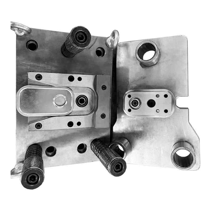
Handle attachment bosses, mounting bracket features, and drain plug bosses are formed in separate stamping operations using progressive compound dies or single-station presses, with dimensional tolerances held to plus or minus 0.3 mm on hole positions for assembly compatibility.
Bottom Bead Rolling and Structural Stiffening
Vacuum cleaner pail housings typically require circumferential beads or ribs rolled into the sidewall and base to increase hoop rigidity — resistance to the inward collapse that would otherwise occur under the negative pressure (partial vacuum) generated inside the pail during operation. Bead rolling is performed by passing the drawn shell between profiled rollers on a bead rolling machine, forming raised or recessed ribs at defined heights on the sidewall without removing material. A properly beaded sidewall can resist collapse pressures of 0.05 to 0.08 MPa below atmospheric (typical operating vacuum for industrial wet-dry vacuums) without permanent deformation.
Stage 5: Seam Welding and Handle Attachment
While many vacuum cleaner pail housings are formed as seamless deep-drawn shells, some designs — particularly larger industrial pails and those with complex cross-sections — are formed from rolled and welded sheet. The welding and attachment stage is therefore a significant process element in certain production line configurations.
Resistance Seam Welding
For pail housings formed from rolled sheet rather than deep-drawn blanks, the longitudinal seam is closed by resistance seam welding — a continuous welding process where the overlapping or butt-joined sheet edges are passed between two rotating copper electrode wheels that apply current and pressure simultaneously, producing a continuous series of overlapping spot welds that form a hermetic seam. Seam welding parameters for 0.6 mm low-carbon steel are typically:
- Welding current: 8,000 to 15,000 amperes, depending on electrode wheel diameter and welding speed
- Electrode force: 2.5 to 4.5 kN applied by pneumatic or servo-controlled electrode arms
- Welding speed: 4 to 10 meters per minute for continuous seam welding of thin-gauge steel pail bodies
- Seam weld quality: Verified by destructive peel test sampling (minimum nugget width 3 times the square root of sheet thickness per ISO 14273) and visual inspection for expulsion, burn-through, and surface discoloration
(Source: ISO 14273:2016 Specimen dimensions and procedure for shear testing resistance spot, seam, and embossed projection welds; AWS C1.1 Recommended Practices for Resistance Welding.)
Handle and Bracket Attachment
Carry handles, hose connector bosses, and mounting brackets are attached to the pail body by resistance spot welding, MIG (GMAW) welding, or mechanical fastening depending on the load requirements and production cost targets. Spot welding of handle attachment brackets uses 4 to 8 weld spots per bracket, each sized to carry the static load of the pail plus contents (typically rated for a minimum static load of 30 to 50 kg for industrial vacuum cleaners) with a safety factor of at least 4:1 against weld shear failure.
Stage 6: Surface Pre-Treatment — Cleaning, Degreasing, and Conversion Coating
Before any surface coating is applied, the formed pail shells must undergo thorough chemical pre-treatment to remove drawing lubricants, mill oils, metalworking residues, iron oxide (flash rust), and any other contaminants that would prevent paint adhesion. The pre-treatment sequence is the quality foundation of the coating system — inadequate pre-treatment is responsible for over 80% of coating failures in the field. (Source: Gardner, G., Industrial Painting and Powder Coating, Hanser, 2010.)
Spray Tunnel Pre-Treatment Sequence
The standard pre-treatment line for vacuum cleaner pail housings is a spray tunnel with 5 to 7 processing zones:
- Alkaline degreasing (Stage 1): Hot alkaline cleaner at 50 to 65 degrees C removes drawing oil, mill scale residues, and fingerprints. Concentration: 2 to 5% alkaline cleaner by volume; contact time: 60 to 120 seconds by spray application.
- First water rinse (Stage 2): Ambient-temperature water rinse dilutes and removes alkaline cleaner from the surface. Rinse water conductivity monitored to below 500 microsiemens/cm to confirm adequate dilution.
- Second water rinse (Stage 3): A second rinse stage ensures complete alkaline removal before conversion coating application, preventing bath contamination and ensuring consistent conversion coating formation.
- Conversion coating — Iron phosphate or Zinc phosphate (Stage 4): The conversion coating chemically reacts with the clean steel surface to form an inorganic crystalline layer that provides corrosion resistance and a micro-rough surface that significantly improves paint adhesion. Iron phosphate (trication process) at 45 to 55 degrees C produces a coating weight of 0.3 to 1.0 g/m2 suitable for indoor and moderate outdoor exposure applications. Zinc phosphate at 50 to 60 degrees C produces a heavier coating weight of 1.5 to 4.5 g/m2 providing higher corrosion resistance for demanding industrial environments.
- Post-rinse passivation (Stage 5): A chromate or chrome-free passivation seal closes the conversion coating crystal structure, further improving corrosion resistance and paint adhesion. Chrome-free passivation (zirconium or titanium-based) is the current standard in most markets due to environmental restrictions on hexavalent chromium under EU REACH Regulation.
- Deionized water final rinse (Stage 6): A final rinse with deionized water (conductivity below 50 microsiemens/cm) removes soluble salts deposited from previous stages that would act as osmotic blistering sites under the coating film.
- Pre-treatment drying oven (Stage 7): Parts exit the spray tunnel and pass through a drying oven at 100 to 130 degrees C to completely evaporate surface moisture before coating application. Residual moisture under a coating causes blistering, particularly in high-humidity environments.
Stage 7: Coating Application — Liquid Paint or Powder Coating
The coating stage applies the protective and decorative surface finish to the pre-treated pail shell. Two primary coating technologies are used in vacuum cleaner pail production lines: liquid paint (typically electrocoat primer followed by liquid topcoat) and powder coating (electrostatic spray of thermosetting powder cured in an oven).
Electrostatic Liquid Paint Application
Electrostatic spray painting uses high-voltage (60 to 100 kV) electrostatic charging of atomized paint droplets to improve transfer efficiency — the proportion of sprayed material that deposits on the workpiece rather than being lost as overspray. Electrostatic liquid spray achieves transfer efficiencies of 65 to 85% compared to 25 to 45% for conventional air-atomized spraying, significantly reducing paint consumption and volatile organic compound (VOC) emissions per unit coated. (Source: Surface Coating Technologies, Federation of Societies for Coatings Technology, 3rd Edition.)
Automated reciprocating spray guns or robotic spray arms apply the liquid paint to the pail shells conveyed through the spray booth on an overhead power-and-free conveyor. Film build targets for vacuum cleaner pail housings are typically:
- Primer coat: 20 to 40 micrometers dry film thickness
- Topcoat: 40 to 80 micrometers dry film thickness
- Total system dry film thickness: 60 to 120 micrometers
Powder Coating Application
Powder coating has become increasingly dominant in vacuum cleaner pail production because it eliminates solvent VOC emissions, achieves one-coat systems (eliminating the primer coat in many specifications), and produces coating thicknesses of 60 to 100 micrometers in a single application pass. Powder is applied by corona-charging spray guns (60 to 100 kV charging voltage) or tribo-charging guns (friction-charging, no external voltage). The electrostatically attracted powder adheres to the grounded workpiece surface uniformly, including complex internal surfaces and recessed areas that are difficult to coat with liquid spray.
Thermosetting epoxy-polyester hybrid powder — the most widely used powder type for metal housing applications — provides excellent adhesion, impact resistance, and moderate outdoor weathering resistance. Polyester-TGIC powder is specified for applications requiring higher UV and weathering resistance. The cured powder coating on vacuum cleaner pails must pass the following minimum performance requirements:
- Cross-cut adhesion: Grade 0 (no flaking) per ISO 2409
- Impact resistance: No cracking or delamination at 80 cm drop weight per ISO 6272 (direct impact)
- Salt spray resistance: No blistering or creep beyond 1 mm from scribe after 240 hours per ISO 9227
- Pencil hardness: Minimum H grade per ISO 15184
(Source: ISO 2409:2020 Cross-cut test; ISO 9227:2017 Salt spray tests; ISO 6272 Impact resistance tests.)
Stage 8: Curing Oven — Developing the Coating's Final Properties
Both liquid paint and powder coating require a thermal curing stage to develop their final mechanical and chemical resistance properties. The curing oven is a critical process element — under-cure produces a soft, chemically sensitive coating that fails adhesion and corrosion resistance tests; over-cure causes yellowing, embrittlement, and loss of impact resistance.
Powder Coating Cure Parameters
Thermosetting powder coatings cure by a crosslinking chemical reaction triggered by heat. The standard cure specification for epoxy-polyester hybrid powder is:
- Peak metal temperature (PMT): 180 to 200 degrees C at the metal substrate surface
- Time at PMT: 10 to 20 minutes — the minimum time the metal must remain at or above the PMT for complete crosslinking
- Oven set temperature: Typically 180 to 220 degrees C air temperature; the actual PMT achieved depends on the thermal mass of the part and the oven dwell time
Temperature uniformity across the oven cross-section is critical — a variation of more than plus or minus 5 degrees C can result in parts at the cool zones being under-cured while parts at the hot zones are over-cured. Modern coating ovens for vacuum cleaner pail lines use convection heating with high-velocity recirculation fans and zoned temperature control to achieve oven uniformity of plus or minus 3 degrees C across the full work zone. (Source: Powder Coating Institute Technical Manual; ASTM D7990 Standard Guide for cure of powder coatings.)
Oven Types and Energy Efficiency
Gas-fired convection ovens are the standard for high-throughput production lines due to their low operating cost and fast recovery time after door opening or line stoppages. Electric infrared ovens provide faster ramp-up heating and are preferred for intermittent production or where gas supply is unavailable. Combined IR/convection hybrid ovens offer the fastest cycle times by using infrared radiation for rapid initial temperature rise and convection for final soak and temperature uniformity, enabling oven lengths to be reduced by 20 to 30% compared to pure convection ovens for equivalent throughput.
Stage 9: Quality Inspection and Testing
A comprehensive quality inspection program is integrated into the production flow at multiple points — incoming material, after forming, after welding, and after coating — to ensure that dimensional, structural, and surface quality standards are met before parts proceed to the next stage or are shipped to the assembly facility.
Dimensional Inspection
Formed pail shells are dimensionally checked at regular sampling intervals using coordinate measuring machines (CMM) or dedicated gauging fixtures that simultaneously verify multiple critical dimensions. Key dimensional checks include:
- Overall pail height: tolerance typically plus or minus 0.5 mm
- Pail body outer diameter at defined heights: tolerance plus or minus 0.3 mm
- Flange diameter and flange width: tolerance plus or minus 0.3 mm for assembly fitment
- Handle hole position: tolerance plus or minus 0.5 mm for handle bracket alignment
- Base flatness: maximum deviation 0.5 mm to ensure stable standing on flat surface
Coating Quality Inspection
After the coating curing oven, 100% visual inspection is performed by trained operators for coating defects including:
- Pinholes and fish-eyes: Small circular defects caused by contamination under the coating, typically from surface oils or silicone contamination of the pre-treatment bath
- Orange peel: Surface texture resembling orange skin, caused by insufficient flow of powder before gelation — indicates cure temperature too high or powder viscosity too high
- Sags and runs: In liquid coating, caused by excessive film build or excessive solvent dilution producing too-low viscosity at application
- Color and gloss variation: Inconsistency within a batch compared to the approved color standard, checked using a spectrophotometer (Delta E tolerance typically below 1.0) and glossmeter (target gloss plus or minus 5 gloss units at 60-degree geometry)
Dry film thickness is checked on all coated parts using calibrated magnetic induction (for steel substrates) or eddy-current (for non-ferrous) thickness gauges per ISO 2808, with a minimum reading frequency of one measurement per 50 production parts or per process adjustment event.
Pressure and Leak Testing
For vacuum cleaner pail housings intended for wet-dry vacuum applications, pressure integrity testing is performed to verify the seam weld and flange-to-body joint against liquid leakage. Hydrostatic pressure testing at 0.1 to 0.15 MPa (above the maximum operating internal positive pressure that can occur during hose blockage events) for a 30-second hold with no leakage is a typical production test requirement for industrial-grade pail housings.
| Inspection Stage |
Check Type |
Method / Standard |
Sampling Frequency |
| Incoming coil stock |
Material certificate, thickness, hardness |
EN 10130 / JIS G3141; micrometer; Rockwell HR30T |
Per coil certificate; 5 thickness readings per coil |
| After blanking |
Blank diameter, burr height, weight |
Caliper measurement; burr gauge; precision scale |
Every 100 blanks; immediately after tool change |
| After final draw |
Shell height, diameter, wall thickness, surface cracks |
CMM; micrometer; visual/MPI inspection |
Every 50 shells; 100% visual for cracks |
| After welding |
Weld nugget, seam continuity, leak test |
ISO 14273 peel test; hydrostatic test |
Destructive: 1 per 500; Leak test: 100% |
| After coating cure |
DFT, adhesion, gloss, color, visual defects |
ISO 2808 DFT; ISO 2409 cross-cut; spectrophotometer |
DFT: 1 per 50 parts; Visual: 100% |
Table 1: Quality inspection summary for vacuum cleaner pail production line. Source: ISO 2409:2020; ISO 2808:2019; ISO 14273:2016; EN 10130:2006.
Stage 10: Final Assembly Preparation and Packaging
The final stage of the production line prepares the finished, coated pail housing for delivery to the vacuum cleaner assembly facility. This stage includes any remaining sub-assembly operations — handle attachment, rubber gasket installation, nameplate riveting, hose connector installation — that can be completed on the pail housing before it is shipped separately from the motor and filter assembly.
Rubber Gasket and Seal Installation
The flanged rim of the pail housing receives a rubber sealing gasket that provides the air-tight seal between the pail body and the vacuum cleaner top assembly (the motor and filter unit). Gasket materials are typically EPDM or NBR rubber, selected for resistance to water, foam, and cleaning chemical exposure in wet-dry vacuum applications. Gaskets are pressed into the flange groove using dedicated pressing fixtures that ensure uniform seating depth of plus or minus 0.2 mm around the full circumference to guarantee consistent sealing force after assembly.
Packaging for Transport
Finished pail housings are nested or stacked in cardboard cartons with separating foam sheets or corrugated card inserts to prevent surface contact that would scratch or deform the coating during transport. Packaging design must accommodate the dimensional envelope of the pail housing including handles, boss protrusions, and hose connectors, while maintaining sufficient packing density to optimize container utilization for international shipping. A standard 20-foot shipping container can typically accommodate 800 to 1,200 pail housings depending on pail diameter and stacking configuration.
Production Line Layout and Equipment Integration
A complete vacuum cleaner pail production line integrates all of the above process stages into a continuous, synchronized manufacturing flow. The physical layout typically follows a linear or U-shaped arrangement driven by material flow logic and factory footprint constraints.
Typical Line Footprint and Throughput Parameters
| Production Stage |
Key Equipment |
Cycle Time (per unit) |
Typical Floor Area |
| Coil feeding and blanking |
Decoiler, straightener, servo feed, blanking press |
0.75 to 1.5 seconds |
60 to 100 m2 |
| Drawing (3 stages) |
3 x drawing presses with transfer automation |
6 to 12 seconds total |
80 to 150 m2 |
| Trimming and flanging |
Rotary trimmer, flanging press |
4 to 8 seconds |
30 to 50 m2 |
| Welding and attachment |
Seam welder, spot welders, riveting stations |
15 to 30 seconds |
50 to 80 m2 |
| Pre-treatment tunnel |
7-stage spray tunnel, drying oven |
8 to 15 minutes (oven travel) |
120 to 200 m2 |
| Powder coating |
Spray booth, corona guns, curing oven |
15 to 25 minutes (oven travel) |
150 to 250 m2 |
| Inspection and packaging |
Visual inspection stations, gauging fixtures, packing line |
20 to 40 seconds |
60 to 100 m2 |
Table 2: Typical process parameters and floor area requirements for a complete vacuum cleaner pail production line. Values are indicative for a line producing 250 mm to 350 mm diameter housings at 1,200 to 2,000 units per shift. Source: Production engineering reference data; line design experience from can and housing production line engineering.
Conveyor System and Line Synchronization
The overhead power-and-free conveyor system is the backbone of the integrated production line, transporting pail shells through the pre-treatment tunnel, coating booth, and curing oven on carrier hooks or fixtures at a controlled speed synchronized to the process requirements of each zone. The conveyor speed through the pre-treatment tunnel is set to provide the required contact time at each spray stage; the speed through the curing oven is set to achieve the required PMT hold time based on oven temperature profile testing using data-logging thermocouples mounted on representative parts.
Our Vacuum Cleaner Pail Production Line Solutions
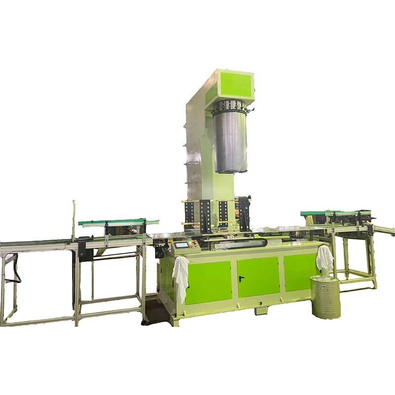
Our Vacuum Cleaner Pail Production Line solutions provide fully integrated, turnkey manufacturing systems covering all stages of the pail housing production process — from coil feeding and multi-stage deep drawing through pre-treatment, powder coating, curing, and quality inspection. Each line is engineered to the specific housing geometry, production rate, material specification, and factory layout requirements of the individual customer, rather than being a standard catalog configuration applied without adaptation.
Our complete equipment range for vacuum cleaner pail production includes:
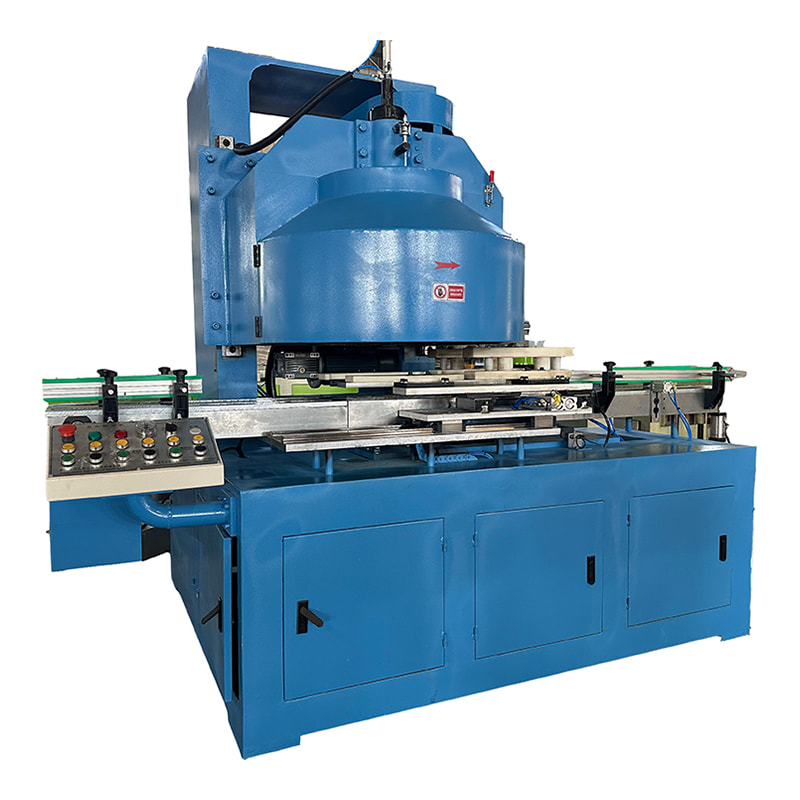
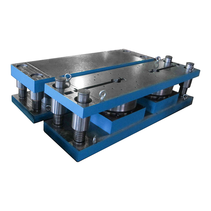
- Coil feeding and blanking systems — hydraulic decoilers, servo-driven straightener-feeder units, and precision blanking presses sized to the blank diameter and production rate, with die designs validated by finite element simulation before manufacture
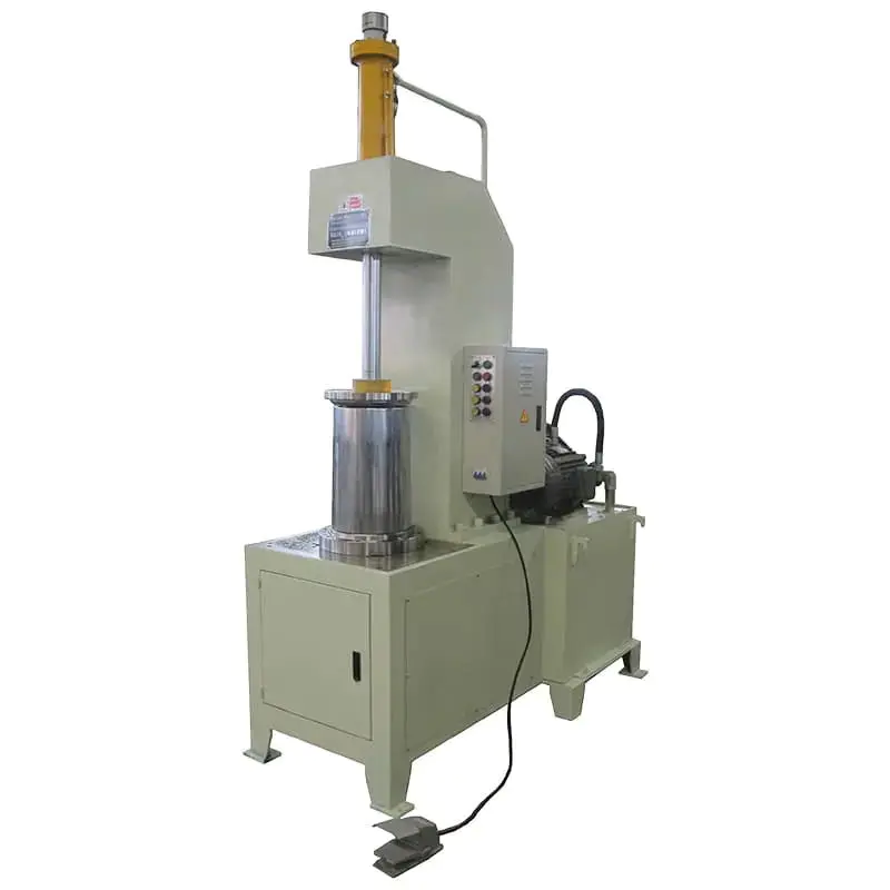
- Multi-stage deep drawing press lines — double-action hydraulic or mechanical transfer presses with programmable blank holder pressure profiles, integrated lubrication systems, and automatic inter-stage transfer for 2- to 4-stage drawing sequences covering pail diameters from 180 mm to 400 mm
- Trimming, flanging, bead rolling, and hole piercing stations — precision rotary trimmers, flanging presses, and multi-roll bead rolling machines engineered to the specific flange geometry and bead pattern of each pail housing design
- Resistance seam welding and spot welding systems — including seam welders for longitudinal pail body seams, multi-gun spot welders for handle and bracket attachment, and fully automated welding cells with parameter monitoring and weld quality data logging
- Chemical pre-treatment tunnel systems — 5- to 7-stage spray tunnels with stainless steel tank construction, automated chemical dosing and monitoring, wastewater treatment systems, and pre-treatment drying ovens integrated in a single pre-treatment module
- Powder coating and liquid paint application systems — electrostatic spray booths with corona or tribo charging guns, automated reciprocating spray equipment or robotic spray arms, and integrated powder recovery systems with filtration efficiency above 99%
- Curing and drying ovens — gas-fired or electric convection ovens with zoned temperature control, high-velocity recirculation fans, and oven uniformity to plus or minus 3 degrees C, sized for the specific part thermal mass and production throughput
- Overhead power-and-free conveyor systems — synchronized conveyor infrastructure linking all process stations with variable speed control, accumulation capability for process time buffering, and hanger/fixture designs matched to the pail housing geometry
Engineering support for new line projects includes process simulation and forming feasibility assessment, tooling design and validation, line layout optimization, commissioning supervision, operator training, and ongoing technical support after production startup. Our production line solutions have been installed and validated in vacuum cleaner and household appliance manufacturing facilities across multiple global markets, with documented compliance to applicable product and process standards.


 +86 13666712509

 English
 русский
 عربى
عربى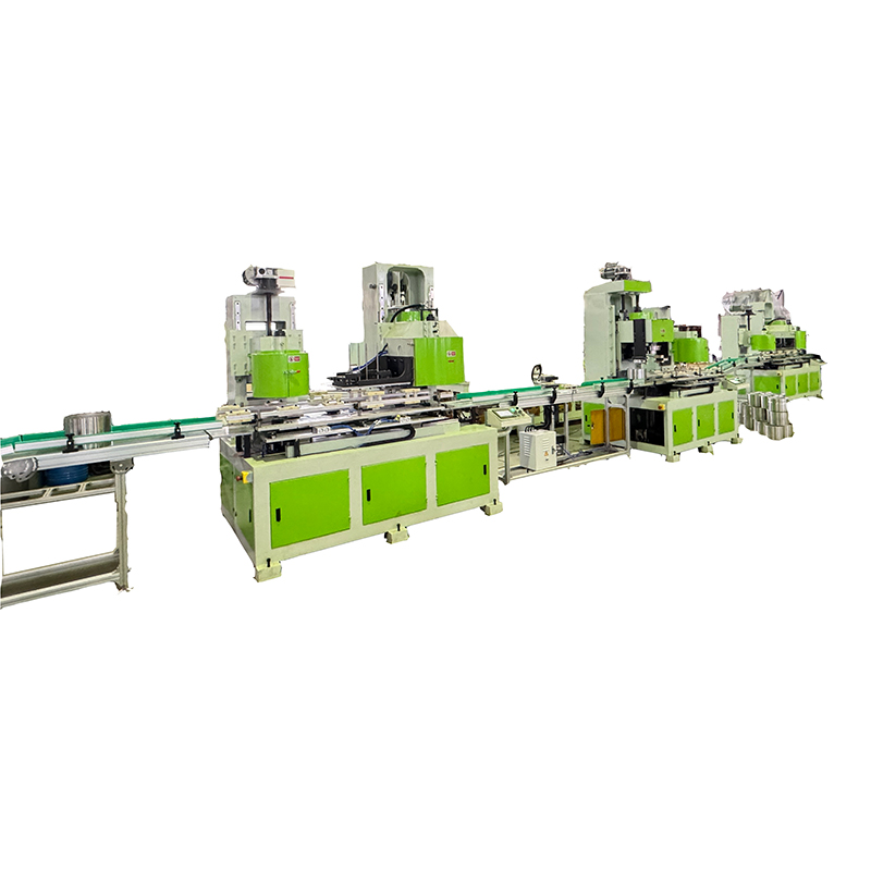



Contact Us