Improving the quality of an 18L pail production line requires a systematic approach targeting five key areas: raw material control, process parameter optimization at each production stage, automated inline inspection, equipment maintenance discipline, and reduction of manual intervention through higher automation. An 18L metal pail production line typically encompasses raw material feeding, sheet metal forming, welding, interior and exterior coating, drying, expanding, seaming, and handle/bail attachment — each stage capable of introducing defects that compound downstream. The highest-impact quality improvements come from tightening process controls at the welding and seaming stages, implementing automated vision inspection systems, and standardizing coating application to eliminate the corrosion and adhesion failures that account for the majority of customer complaints in chemical, food, and paint pail production.
Control Raw Material Quality Before It Enters the Line
Quality problems in finished 18L pails frequently originate in incoming raw materials — not in the production process itself. Implementing rigorous incoming inspection prevents defective material from contaminating production runs and generating scrap at downstream stages.
- Sheet metal thickness verification — 18L pails are typically produced from tinplate or electrolytic chromium-coated steel (ECCS) in the range of 0.18–0.28 mm thickness. Incoming coil stock should be measured at the coil edges, center, and multiple cross-sections using a calibrated ultrasonic or contact thickness gauge. Thickness variation exceeding ±0.01 mm across a coil can cause inconsistent forming, weld penetration variation, and seam tightness defects.
- Tin coating weight verification — for tinplate stock, verify that the tin coating weight (typically 2.8/2.8 g/m² to 5.6/5.6 g/m²) meets specification. Underweight tin coating accelerates internal corrosion in chemical and food pails, leading to product contamination and field failures.
- Surface inspection — visually and mechanically inspect incoming sheet stock for rust spots, oil contamination, surface scratches, and coil set (permanent curvature from coil storage) before feeding. Surface defects that pass through the line appear as coating adhesion failures and corrosion initiation points in finished pails.
- Coil set correction — install a precision straightener/leveler with sufficient roller passes (typically 7–11 rolls) before the blanking station to eliminate coil set and ensure flat, consistently fed blanks. Curved blanks produce non-circular formed bodies that cause seaming defects and non-uniform seam overlap.
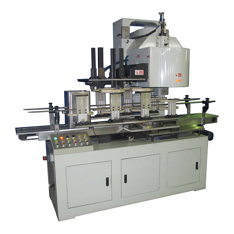
Optimize the Welding Stage: The Most Critical Quality Point
The side seam weld of the pail body is the single most common source of structural defects in 18L pail production. A defective weld produces leaking, structurally weak pails that fail in service — the most costly quality failure mode. Weld quality is governed by four variables that must all be held within tight tolerances simultaneously.
Resistance Seam Welding Parameter Control
- Welding current — must be calibrated to the specific sheet thickness and tin coating weight. Too low produces cold welds (insufficient fusion, visible as grey or dull seam appearance); too high causes expulsion (molten metal splash, burn-through, and porosity). For 0.22 mm tinplate, welding current is typically set in the range of 1,200–1,800 A depending on welding wire diameter and speed.
- Electrode wire speed and condition — the copper electrode wire that carries current to the weld zone must be fed at a consistent, calibrated speed and must be free of tin contamination buildup. Wire that is heavily contaminated with tin from previous welds increases contact resistance unpredictably, causing weld energy fluctuations. Replace or re-clean the wire conditioning system according to a fixed maintenance interval — not on a "when it looks bad" basis.
- Overlap width consistency — the body blank's side seam overlap must be held to a tight tolerance (typically 0.4–0.6 mm overlap for resistance seam welding). Use precision forming and feeding guides with regular dimensional checks — overlap variation of even 0.1 mm can shift weld quality from acceptable to rejectable.
- Weld quality monitoring — install an inline weld monitor that measures actual welding current and voltage on every cycle and alerts operators when parameters deviate from the set window. This converts weld quality from a sampled inspection item to a 100% monitored characteristic.
Post-Weld Inspection and Stripe Coating
After welding, the side seam is exposed bare metal on the interior surface where the tin coating has been burned away by the welding heat. Apply an interior stripe coat of epoxy or organic lacquer over the weld seam using an inline stripe coating station with a calibrated nozzle. The stripe coat width should cover the full heat-affected zone — typically 6–10 mm on each side of the weld centerline — and coat weight should be verified gravimetrically at startup and after each shift change.
Improve Coating Application for Corrosion Protection and Adhesion
Interior and exterior coating quality directly determines the pail's service life and its suitability for food, chemical, and pharmaceutical contents. Coating defects are the leading cause of corrosion-related product returns in 18L pail applications.
Coating Weight Consistency
Interior coating weight for 18L food-grade or chemical pails is typically specified at 3–8 g/m² dry film. Under-weight coating leaves exposed metal that corrodes rapidly when in contact with acidic or chloride-containing products. Over-weight coating increases cost, extends drying time, and can cause solvent entrapment blistering. Measure coating weight on production samples at least every 2 hours using gravimetric methods (weigh before and after stripping the coating chemically) and adjust spray parameters to maintain coating weight within ±10% of the target value.
Oven Temperature Profile Verification
Undercured coating (insufficient drying oven temperature or time) is a primary cause of coating adhesion failure and solvent contamination of food or pharmaceutical contents. Run a thermal profile measurement through the drying oven using a calibrated data logger at least once per week and after any oven repair or belt speed change. The metal substrate temperature must reach the coating supplier's specified peak metal temperature (PMT) — typically 180–210°C for 10–20 seconds for standard epoxy-phenolic interior coatings — and this temperature must be achieved at both the hottest and coldest points of the oven zone.
Porosity Testing of Interior Coatings
Test interior coatings for porosity (pinholes and holidays) using an electrolytic porosity tester (enamel rater) on finished pails sampled from the production run. A result of fewer than 50 milliamperes per pail is typically acceptable for standard chemical pails; food-contact applications may require tighter limits. Porosity above specification indicates coating weight deficiency, substrate contamination, or curing problems that must be traced and corrected before the production run continues.
Tighten Seaming Quality to Prevent Leakage
The double seam that joins the pail base to the body is the second most common source of structural defects after the side seam weld. A leaking base seam causes product loss, contamination, and regulatory non-compliance in food and chemical applications.
- Seaming roll setup and teardown checks — measure the critical seam dimensions (seam width, seam thickness, countersink depth, and body hook length) at the start of every production shift, after any tool change, and after any machine stoppage exceeding 30 minutes. Use calibrated seam scope measurements, not visual inspection alone.
- Seam cross-section teardown — conduct destructive seam teardown analysis on a minimum of 3 pails per shift per seaming head, measuring actual hook lengths, overlap percentage, and tightness rating. The overlap percentage should be ≥50% and body hook length within the tolerance defined by the relevant standard (e.g., SEFEL or equivalent).
- Compound application verification — the sealing compound applied to the end panel curl must be evenly distributed around the full circumference at the specified weight. Check compound coverage on teardown samples — voids or uneven distribution in the compound are a direct cause of seam leakage.
- Pressure leak testing — implement 100% air leak testing of finished pails by pressurizing to 0.3–0.5 bar and submerging in water or applying soap solution to the seam areas. Any bubble formation indicates a seam defect requiring rejection and root cause investigation.
Implement Automated Inline Inspection Systems
Manual sampling inspection cannot detect all defect types at production line speeds of 40–80 pails per minute typical of modern 18L pail lines. Automated inline inspection systems provide 100% coverage and immediate rejection of non-conforming pails without relying on human reaction time.
| Inspection System |
Defects Detected |
Detection Method |
Installation Point |
| Weld monitor |
Cold welds, burn-through, expulsion |
Current/voltage monitoring per weld cycle |
Welder station |
| Machine vision system |
Surface dents, print registration errors, label defects, missing components |
High-speed camera array with image processing |
Post-forming, post-printing |
| Air leak tester |
Seam leaks, base panel pinholes |
Internal pressurization with pressure decay or bubble test |
Post-seaming station |
| Dimensional check system |
Out-of-round body, height variation, flange defects |
Laser profilometer or contact gauging |
Post-expanding station |
| Handle/bail presence sensor |
Missing or incorrectly assembled bail wire/handle |
Photoelectric or inductive proximity sensor |
Post bail attachment station |
Recommended inline inspection systems for 18L pail production lines, covering each major defect category and production stage.
Reduce Manual Intervention Through Higher Automation
Every manual handling step in a production line introduces variability — and variability is the enemy of consistent quality. Upgrading manual or semi-manual operations to fully automated processes consistently reduces defect rates, particularly for surface-sensitive operations like coating and printing.
- Automated conveyor systems — replacing manual pail transfer between stations with synchronized conveyor systems eliminates the denting, scratching, and coating damage caused by operators handling freshly coated or printed pails. Gentle, consistent transfer also prevents the out-of-round deformation that causes seaming problems at downstream stations.
- Robotic operating arms for stacking and palletizing — robotic palletizers handle finished pails at consistent orientations and stack heights without the product damage that occurs when operators manually stack pails under production pressure. They also maintain consistent pallet patterns that prevent stack collapse during transport.
- Automatic parameter adjustment systems — equip the welding station, coating booths, and drying ovens with closed-loop control systems that automatically compensate for ambient temperature changes, material batch variation, and equipment drift. A ±5°C ambient temperature change in summer versus winter can shift weld quality and coating cure state enough to produce defects if parameters are not automatically adjusted.
- Automated lubricant application — the blanking and forming dies require consistent lubrication to prevent galling, scoring, and surface damage on formed pail bodies. Replace manual lubrication (which is often over- or under-applied) with automated spray lubrication systems that apply a precise, consistent lubricant film at every forming cycle.
Establish a Preventive Maintenance Schedule for Critical Tooling
Tooling wear is a major and often underestimated contributor to quality degradation on 18L pail lines. As forming dies, seaming rolls, and welding electrodes wear, they produce increasingly non-conforming pails before operators notice the trend and intervene.
- Seaming roll replacement intervals — establish a fixed replacement schedule for first-operation and second-operation seaming rolls based on the number of ends processed (not on calendar time). A typical replacement interval for seaming rolls on a high-speed line is every 1–3 million ends, depending on the material hardness and seaming speed. Track production counts per set of rolls and replace before the degradation curve begins to affect seam dimensions.
- Forming die inspection and regrinding — inspect blanking dies and body-forming tooling for edge chipping and surface scoring at scheduled intervals. Chipped blanking die edges produce burrs on the blank that damage the forming tooling downstream and create sharp edges on finished pails that cut seaming compound and cause seam leakage.
- Electrode wire and wheel maintenance — for resistance seam welders, maintain the copper electrode wire conditioning system (groove depth, cleaning, and tension) according to manufacturer specifications. Electrode wheel diameter should be measured regularly; a worn wheel with reduced diameter changes the effective contact pressure and weld speed, both of which affect weld quality.
- Expanding tooling concentricity check — the expanding station that sets the final body diameter must maintain concentricity within ±0.2 mm to ensure consistent flange geometry for the seaming station. Check concentricity quarterly and after any crash or machine stoppage event.
Use Statistical Process Control to Identify Trends Before They Become Defects
Reactive quality control — inspecting and rejecting finished pails after they are produced — is the least efficient approach to quality management. Statistical process control (SPC) shifts the focus to monitoring process variables in real time so that corrective action can be taken before defects are produced.
- Control charts for critical dimensions — plot seam width, seam thickness, body height, and flange diameter measurements on X-bar and R control charts. A process consistently producing measurements trending toward the upper or lower control limit is giving early warning of tooling wear or setup drift that will produce rejects if not corrected — typically 30–60 minutes before defects appear in end-of-line inspection.
- Process capability analysis — calculate Cpk indices for critical quality characteristics. A Cpk of ≥1.33 indicates a capable, well-centered process; values below 1.0 indicate the process cannot consistently produce conforming output and require immediate engineering investigation. Conduct capability studies whenever a new material batch, tooling set, or process parameter change is introduced.
- Defect rate tracking and Pareto analysis — record every defect by type, station of origin, and shift. Monthly Pareto analysis of defect data identifies which defect type and which production stage generates the highest total defect count — focusing improvement resources where they deliver the greatest quality return per hour of engineering effort invested.


 +86 13666712509

 English
 русский
 عربى
عربى



Contact Us