To properly use an automatic can sealing machine, follow a structured sequence: verify machine setup and tooling for the can format being run, complete the warm-up and pre-production checks, calibrate seaming roll pressure through setup cans and teardown measurements, release the machine for production with continuous seam quality monitoring, and follow a defined shutdown and cleaning procedure at the end of each run. Skipping or shortcutting any of these stages is the most common source of seam quality failures, production downtime, and premature tooling wear in metal can, drum, and pail manufacturing operations.
Automatic can seaming machines integrate multiple precision-coordinated modules — conveying, positioning, seaming, and inspection — all driven by servo motors and managed by a central control system. Each module must be correctly configured and operating within specification before production begins. Unlike manual or semi-automatic seaming, the automated nature of these machines means that a misconfiguration that produces a defective seam does so consistently across every can in the run until the fault is identified and corrected. A single incorrectly set seaming roll pressure can compromise thousands of seams before the defect is detected without a rigorous setup and verification procedure.
This guide covers every stage of correct automatic can seaming machine operation — from pre-run preparation through production monitoring to post-run maintenance — with the specific data and measurement benchmarks needed to verify that each step has been completed correctly.
Understanding the Machine's Functional Modules Before Operating
Effective operation of an automatic can seaming machine requires a working understanding of what each integrated module does and how it contributes to the final seam quality. Operators who understand the function of each component are better equipped to recognize early signs of misadjustment and respond appropriately before seam quality is compromised.
The Conveying Module
The conveying module transports filled can bodies from the upstream filler or staging area to the seaming station. It typically consists of an infeed conveyor, timing screws or star wheels that separate and space individual cans, and a discharge conveyor that moves sealed cans downstream for coding, labeling, or palletizing. Conveyor speed must be synchronized precisely with the seaming head cycle rate — a mismatch of even a fraction of a second produces either stacking jams or seaming cycles without a can in position, both of which interrupt production and can damage tooling.
The Positioning Module
Once a can body arrives at the seaming station, the positioning module — comprising a can lifter, turntable pocket, and chuck — raises the can to the correct seaming height and holds it rigidly while the seaming rolls orbit around the seam junction. The chuck descends onto the lid, and the lifter pad engages the bottom of the can body, creating a clamping force that prevents the can from moving vertically or rotating during the seaming cycle. Incorrect chuck or lifter positioning by as little as 0.5 mm affects the countersink depth and seam geometry, producing dimensions that may be outside specification even when roll pressure is correctly set.
The Seaming Module
The seaming module contains the first-operation and second-operation seaming rolls, which perform the two distinct forming stages that create a hermetic double seam. The first-operation roll curls the lid flange around the can body flange to form the preliminary interlock. The second-operation roll then compresses and irons this interlock to create the final tight, hermetic seam. Each roll is mounted on a precision bearing assembly and driven to engage the seam junction at a precisely controlled pressure and contact geometry.
The Inspection Module
Advanced automatic seaming machines include an integrated inspection module that uses sensors, vision systems, or mechanical gauges to verify seam dimensions or detect gross defects on every can immediately after seaming. Cans that fail the automated inspection are diverted from the production stream before reaching downstream packaging. However, automated inspection does not eliminate the need for manual seam teardown inspections — it supplements them by catching obvious defects that can be detected non-destructively, while teardown inspections verify the internal seam geometry that cannot be seen from the outside.

Pre-Production Setup: Tooling Verification and Configuration
Every time the machine is configured for a different can format — different diameter, height, lid type, or material gauge — a full tooling setup and verification must be completed before production begins. Even when running the same format as the previous shift, tooling must be re-verified if components were removed for cleaning or maintenance.
Confirm the Correct Tooling Set Is Installed
Each can format requires a matched set of seaming rolls, chuck, and base plate sized for that format's specific dimensions. Seaming roll profiles are machined to precise radii that correspond to the lid curl geometry for a specific can diameter. Using a roll profile intended for a different diameter — even one close in size — produces a seam with incorrect cover hook dimensions that will not meet specification.
- Check the tooling identification number on each installed seaming roll, chuck, and base plate against the format's tooling specification sheet.
- Inspect each seaming roll for visible wear, scoring, or chipping in the groove profile. Any surface damage on the roll contact surface requires roll replacement before setup continues.
- Verify that all tooling fasteners — roll mounting bolts, chuck retaining screws, base plate clamps — are correctly tightened to the specified torque values. Loose tooling produces inconsistent seam dimensions and can cause catastrophic tool release at operating speed.
Set the Chuck Height and Countersink Depth
The chuck must be positioned at a height that produces the specified countersink depth when the lid is clamped in the seaming position. Countersink depth is measured from the top of the seam to the lid panel and directly affects the cover hook length. Most standard double seam specifications call for a countersink depth within ±0.1 mm of the nominal value for the can format being run.
Use a dial indicator gauge to measure the chuck face position relative to the seaming head reference surface. Compare this measurement to the format's setup sheet value and adjust the chuck height mechanism until the measurement is within specification.
Configure the Seaming Roll Positions
Seaming roll position — the distance from the roll groove center to the chuck axis — controls the pressure applied to the seam during each operation. Set initial roll positions to the values specified on the format's setup sheet as a starting point. These values are not the final settings; they are the starting point from which fine-tuning is performed through setup cans and teardown measurements.
On machines with digital roll position readouts or servo-controlled roll positioning, enter the setup sheet values directly into the control system. On machines with mechanical adjustment and manual dial indicators, set each roll to its specified position and lock the adjustment mechanism before proceeding.
Verify the Feed System Configuration
- Set the lid magazine to the correct position for the lid diameter being run. The magazine must align the lid centrally with the lid feed mechanism so lids feed singly and squarely into the seaming station.
- Adjust the infeed conveyor guide rails to the can body diameter plus a clearance of 1 to 2 mm per side — sufficient to allow free can movement without permitting lateral tipping or cross-tracking.
- Load the lid magazine with a small quantity of lids — typically 20 to 30 — for the setup phase. Do not fill the magazine completely until after the setup is confirmed, to avoid contaminating the magazine with setup-phase reject lids.
Machine Warm-Up and Pre-Run Safety Checks
Starting a seaming machine cold and immediately running production is one of the most common causes of early-shift seam quality problems. Thermal expansion of the machine frame, seaming head, and tooling changes the effective roll positions and chuck height from their cold-state measurements. Most automatic seaming machine manufacturers specify a warm-up period of 15 to 30 minutes at operating speed before the first setup cans are run.
Safety Checks Before Power-On
- Verify that all access guards and safety panels are correctly installed and their interlocks are engaged. Do not bypass or defeat any safety interlock — automatic seaming machines operate at speeds and forces that make direct contact with moving seaming rolls or spinning chucks immediately dangerous.
- Check lubrication levels in all oil reservoirs and verify that the centralized lubrication system (if equipped) is primed and functional. Running a seaming machine with insufficient lubrication at startup causes rapid bearing wear that is not immediately apparent but shortens tooling life significantly.
- Clear the machine of any tools, rags, or foreign objects left inside the machine from previous maintenance work. A foreign object inside the seaming station at startup can cause catastrophic damage to the seaming head and tooling.
- Verify that the compressed air supply (where applicable for pneumatic components) is within the specified pressure range — typically 0.5 to 0.7 MPa (73 to 102 psi) — and that the air is clean and dry.
- Confirm that the e-stop buttons are accessible and functional by testing each one before starting the machine at operating speed.
Warm-Up Sequence
- Power on the machine and allow the control system to complete its initialization sequence. Verify that no fault codes are present on the HMI display before proceeding.
- Start the machine at a reduced speed — typically 30 to 50% of the rated production speed — and run it without cans for 5 minutes while listening for any abnormal sounds that may indicate a tooling installation problem.
- Increase to full operating speed and continue running without cans for the remaining warm-up period specified in the machine manual.
- After the warm-up period, re-check that all roll position indicators and chuck height measurements still correspond to the setup sheet values. Thermal expansion may have shifted these measurements slightly, requiring fine adjustment before setup cans are run.
Running Setup Cans and Performing Seam Teardown Measurements
Setup cans are the most critical step in the correct use of an automatic can seaming machine. This is the process by which the machine's roll pressure settings are verified and fine-tuned against the actual seam dimensions produced — not against theoretical setup sheet values. No automatic seaming machine should be released for production without at least three consecutive setup cans measuring within specification on all seam parameters.
Running the Setup Cans
- Load empty can bodies and lids — or water-filled test cans if the production product is not yet available — and run a minimum of 5 to 10 cans at full operating speed.
- Remove 3 cans from the setup run at regular intervals. Mark each can with its sequence number (can 1, can 2, can 3) and the date, time, and machine number for traceability.
- Set these cans aside for teardown measurement. Do not release any setup cans into the production stream — they must be segregated and confirmed as setup material.
Seam Teardown Measurement Procedure
Seam teardown involves physically cutting through the seam to expose and measure its internal geometry. The following parameters must be measured and recorded for each setup can:
Key double seam parameters measured during teardown inspection, with typical specification ranges for standard steel cans
| Seam Parameter |
What It Measures |
Typical Nominal Range |
Effect if Out of Range |
| Seam thickness |
Total compressed thickness of all seam layers |
1.0–1.3 mm (varies by material gauge) |
Too thick: loose seam; Too thin: metal fracture risk |
| Seam width (height) |
Vertical height of the completed double seam |
2.8–3.5 mm (format dependent) |
Too narrow: insufficient hook; Too wide: loose interlock |
| Cover hook |
Length of lid flange folded into the seam |
1.8–2.4 mm |
Too short: risk of seam opening under pressure |
| Body hook |
Length of can body flange folded into the seam |
1.9–2.5 mm |
Too short: reduced overlap; leakage risk |
| Overlap |
Length of cover hook and body hook interlock |
Minimum 1.1 mm (typically 45–55% of seam width) |
Too low: critical hermetic seal failure risk |
| Countersink depth |
Distance from top of seam to lid panel surface |
3.0–3.5 mm (format dependent) |
Incorrect depth indicates chuck height misadjustment |
| Tightness rating |
Degree of wrinkle in the cover hook |
75–100% (higher is tighter) |
Below 75%: insufficient second-operation pressure |
Measure each parameter at a minimum of three positions around the seam circumference — typically at 0°, 120°, and 240° — and at the side seam junction on welded can bodies. Record all measurements on the setup record form for that run. If any measurement falls outside specification, make the indicated roll pressure or chuck height adjustment and run another set of setup cans before re-measuring.
Adjustment Logic Based on Teardown Results
- Seam too thick (loose): Tighten the second-operation roll by moving it closer to the chuck axis in small increments of 0.05 to 0.10 mm. Re-run setup cans and re-measure after each adjustment.
- Cover hook too short: Move the first-operation roll inward to increase curl forming pressure. Short cover hook is the most common indicator of insufficient first-operation pressure.
- Wrinkled or deformed lid: First-operation roll pressure is too high. Back the roll out by 0.05 mm increments and re-measure.
- Countersink depth out of range: Adjust the chuck height mechanism. Deeper countersink requires raising the chuck; shallower countersink requires lowering it.
- Variation between positions around the circumference: Indicates seaming head concentricity or chuck alignment problem. Check dial indicator readings at the chuck face in multiple positions around the axis.
Releasing the Machine for Production and Initial Monitoring
Once three consecutive setup cans have measured within specification on all seam parameters, the machine can be released for production. The release is not the end of operator involvement — it is the transition from intensive setup monitoring to ongoing production monitoring.
Production Release Checklist
- Sign and date the setup record form, confirming that all seam measurements met specification and that the machine was released for production at a specific time. This record forms part of the production quality documentation for traceability purposes.
- Fill the lid magazine to its full capacity.
- Confirm with the upstream filler that product is available and that the filling level is within the headspace specification for the can format. Overfilled cans compress the sealing compound during seaming; underfilled cans may not support the can body correctly under the seaming forces.
- Start the production run at the rated speed and observe the first 50 to 100 cans for any visible seam irregularities — wrinkles, uneven seam height, or marks on the can body from guide rail contact.
In-Production Seam Monitoring Schedule
Seam quality must be verified at regular intervals throughout the production run, not just at startup. The following minimum monitoring schedule is recommended for continuous production operations:
Minimum recommended seam monitoring activities and frequencies during continuous automatic can seaming production
| Monitoring Activity |
Minimum Frequency |
Who Performs It |
Action if Out of Spec |
| Visual seam inspection |
Every 15 minutes |
Machine operator |
Flag and investigate immediately |
| External seam dimension check |
Every 30 minutes |
Operator or QC technician |
Stop production; investigate and adjust |
| Full seam teardown measurement |
Every 60 minutes |
QC technician |
Stop production; re-setup required |
| Pressure decay leak test |
Every 1,000 cans minimum |
QC technician |
Stop production; investigate seam integrity |
| Feed system inspection |
Every 2 hours |
Operator |
Clean guides and tracks at next scheduled break |
| Lid magazine refill and inspection |
As needed, inspect each batch loaded |
Operator |
Reject damaged or out-of-spec lids before loading |
Responding to Mid-Production Process Changes
Any of the following events during a production run must trigger an immediate additional seam teardown inspection — even if the regular scheduled inspection interval has not yet elapsed:
- A feed jam or machine stop that required manual intervention to clear
- A change in the lid or can body batch or material lot number
- Any adjustment made to the seaming roll positions, chuck height, or conveyor speed
- Any machine fault code that required reset to resume production
- A noticeable change in machine noise, vibration, or any other observable machine behavior
Operating the Control System: Key HMI Functions for Operators
Modern automatic can seaming machines are controlled through a human-machine interface (HMI) that provides access to machine parameters, production data, fault history, and diagnostic tools. Operators must be familiar with the key HMI functions relevant to daily operation — not just the start and stop buttons.
Production Speed Control
The HMI allows operators to set the machine's production speed in cans per minute (CPM). The rated speed is the maximum speed at which the machine can produce seams within specification under optimal conditions. Operating consistently at or near the rated maximum speed without adequate setup verification and monitoring increases the risk of seam quality drift, because there is less time for each module to complete its positioning and forming sequence accurately. For new operators or new can formats, starting at 80% of rated speed and verifying seam quality before increasing to full speed is a recommended practice.
Recipe Storage and Recall
Most modern seaming machine control systems allow machine setup parameters — roll positions, chuck height, conveyor speed, inspection thresholds — to be saved as named recipes for each can format. When switching between formats, recalling the saved recipe restores all parameters to the last confirmed good settings for that format, significantly reducing setup time and the risk of manual entry errors. Recipe parameters should be verified by running setup cans and performing teardown measurements even when loading a previously saved recipe, as tooling wear and thermal conditions mean that recalled parameters are a starting point rather than a guarantee of correct seam geometry.
Fault Code Monitoring and Response
The HMI displays active fault codes and maintains a fault history log. Operators should review the fault history at the start of each shift to identify any faults that occurred during the previous shift that were reset without investigation. A pattern of recurring fault codes — even minor ones — is an early warning of a developing mechanical or electrical issue that will eventually escalate to a production-stopping failure if not addressed.
When a fault code appears during production, the correct procedure is to record the fault code and machine state before resetting. Resetting without recording prevents the maintenance team from identifying patterns and root causes in fault history analysis.
End-of-Run Shutdown and Cleaning Procedures
Correct shutdown and cleaning at the end of each production run is as important to machine longevity and next-run setup quality as correct startup. Machines that are not properly cleaned at run end accumulate product residue, compound debris, and metal particles that degrade seam quality, increase feed jam frequency, and accelerate wear on precision tooling surfaces.
Shutdown Sequence
- Stop the product feed from the upstream filler and allow the machine to run through and seal all remaining cans in the feed system before stopping the seamer. Do not stop the seamer with filled, unsealed cans in the machine if it can be avoided — these must be removed and either resealed or discarded as non-conforming product.
- Run the machine at reduced speed until the feed system is empty of cans and lids, then stop the machine using the normal stop function (not the e-stop, which should be reserved for emergency conditions).
- Remove all remaining lids from the magazine. If the lids will be used for the next run of the same format, store them in a sealed container in a clean, temperature-controlled area. Do not return lids that have been exposed to product contamination, moisture, or physical damage to the magazine.
- Power off the machine after confirming that all motion has stopped and the machine is in a safe state.
Post-Run Cleaning
- Feed tracks and conveyor surfaces: Remove all product residue, compound drips, and metal debris from all surfaces using appropriate cleaning agents and tools. Product residue in the feed track is the most common cause of the first jam on the following shift's startup.
- Seaming roll surfaces: Wipe the seaming roll groove surfaces with a clean cloth to remove compound residue and metal debris. Metal particles adhered to the roll groove are transferred to the seam on the next startup and can score the seam material or produce point-load deformation of the seam geometry.
- Chuck faces: Clean the chuck face and pilot surfaces. Compound buildup on the chuck face alters the effective countersink depth on the next run and can cause the lid to stick to the chuck during the seaming cycle.
- Turntable pockets and lifter pads: Remove any product, compound, or debris from the can support surfaces. These surfaces must be clean and undamaged for can bodies to seat at the correct height at the start of the next run.
- Sensor lenses: Wipe all presence sensor lenses with a lint-free cloth. Contaminated sensor lenses are a leading cause of sporadic false stop faults on machine startup.
Post-Run Lubrication
Apply lubrication to all manual lubrication points at the end of each shift according to the machine's lubrication schedule. Post-run lubrication — rather than pre-run only — ensures that bearing surfaces are protected during the idle period between shifts, when residual heat and lack of oil circulation create optimal conditions for corrosion and lubricant film breakdown on precision surfaces.
Operator Safety Rules Specific to Automatic Can Seaming Machines
Automatic seaming machines are high-speed, high-force industrial equipment. The seaming rolls apply forces of several hundred newtons to form the seam, and the machine cycles at rates of 100 to 1,200 cans per minute depending on the model and format. Direct contact with moving components during operation can cause severe injury. The following safety rules must be observed at all times by everyone working near an operating seaming machine:
- Never reach into the machine while it is in motion. If a jam or foreign object must be removed from inside the machine, use the e-stop to bring the machine to a complete stop, wait for all motion to cease, and verify the machine is in a safe state before reaching inside any guard opening.
- Never bypass, disable, or tape over any safety interlock or guard. Safety interlocks exist because the consequences of contact with moving seaming machine components are severe and immediate. A bypassed interlock that prevents one inconvenient machine stop may allow a later contact injury.
- Perform any tooling adjustment or maintenance only with the machine in a locked-out, tagged-out (LOTO) state according to the facility's LOTO procedure. For seaming machine tooling work, the energy isolation must include the main power disconnect, pneumatic supply isolation, and verification that stored energy in capacitors and springs has been safely dissipated.
- Wear hearing protection when working near operating seaming machines. Continuous exposure to seaming machine noise levels of 85 dB or above — common at production speeds above 300 CPM — causes cumulative hearing damage over time.
- Keep loose clothing, hair, and jewelry secured and away from the machine's infeed and discharge areas, where rotating timing screws, star wheels, and conveyors present entanglement hazards.
- Report any machine behavior that deviates from normal — unusual sounds, vibration, repeated fault codes, or seam quality changes — to maintenance personnel immediately rather than attempting to diagnose or adjust the machine beyond the scope of the operator's authorized tasks.
Key Operational Data to Record for Every Production Run
Maintaining accurate production records for every run on the seaming machine serves multiple purposes: it provides traceability for product quality, supports root cause analysis when defects are discovered, and creates a historical dataset that allows trends in machine performance to be identified before they produce quality failures. At a minimum, the following data should be recorded for every production run:
- Date, shift, machine number, and operator name
- Can format and product description
- Lot numbers of can bodies and lids used
- Machine speed (CPM) at which production was run
- Setup seam teardown measurements and the time of setup completion
- All in-production seam teardown measurements with time stamps
- Any fault codes that occurred during the run, with time, fault type, and action taken
- Any adjustments made to machine settings during the run, with the before and after values
- Total cans produced and number of rejects or non-conforming cans identified
- Time of run completion and any observations about machine condition at shutdown
A complete, accurate production record is not a bureaucratic requirement — it is a quality assurance tool that enables the production team to identify when during a run a seam quality issue began, which cans are affected, and what machine condition or input material change triggered the problem. Facilities that maintain detailed run records consistently resolve quality incidents faster and with less product quarantine than those that rely on operator memory or incomplete records.


 +86 13666712509

 English
 русский
 عربى
عربى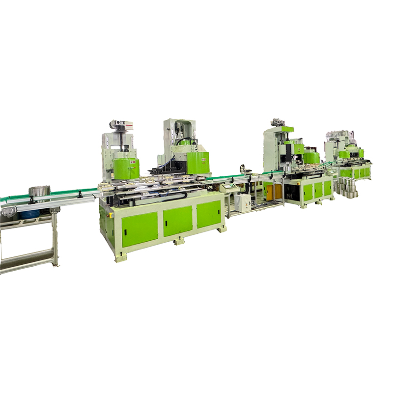

Contact Us